Boris T. Fedosov
Rudny Industrial Institute,
Rudny, Kazakhstan
About author
UDC 681.51.01
F338
The present short description of VisSim is intended for prestress acquaintance to the program which is resulted in the methodical manual on execution of nine laboratory works. Complete offlain the manual version is contained in an applied file, the link for which loading is given more low.
The manual is executed with units of animation in the form of the electronic book of a format chm which can be viewed on any computer by standard tools of an operating system of Windows.
Concept "model" rather broad and multisemantic. It is possible to state, that the person, often not thinking about it, in a life all time creates and uses various models: ambient space, behaviour of other people, physical and technical objects etc. to gain practical favour. It is possible to say, that mapping of a reality by consciousness of the person is to some extent simulation. For example, transferring road, we simulate motion of the coming nearer car to predict, whether we will have time to transfer safety, and to select the correct solution.
In a science and engineering model can be:
Simulation of technical objects and systems is spent to determine properties and characteristics of designed systems even before their manufacture and if necessary to correct, update their structure and parametres. It allows to gain the project of serviceable system which should not be finished essentially when it will be manufactured. Thus, simulation devides out and reduces the price of process of projection and implementation of systems and objects.
Besides, on system model it is possible to muster its behaviour in such requirements and regimes for which the system is not intended so that and to what aftereffects it will result the nobility as it will lead herself. It is obvious, that such experiments on the hardware system can be not only roads, but also are unsafe, while simulation allows to gain the necessary information on process or system without superfluous expenditures and, the main thing, without negative aftereffects.
Program VisSim is intended for construction, examination and optimisation of virtual models of physical and technical objects, including controls systems. VisSim it is an abbreviation of expression Visual Simulator - visual, perceived by sight, the environment and a means of modeling..
Program VisSim, is developed and advanced by company Visual Solutions (USA) [1]. This program - powerful, convenient in usage, compact and an effective tool of simulation of physical and technical objects, systems and their units.
The program gives the person a developed graphic interface, using which, the researcher creates model from virtual units with some extent of conditionality the same as if he built the hardware system of the present units. It allows to create, and then to research and optimise models of systems of a broad band of complexity.
At description and the subsequent construction of model in the environment of VisSim there is no necessity to record and solve differential equations, program it will make itself on offered it the researcher to structure of system and parametres of its units. Outcomes of the solution are injected in a visual graphic form. Therefore the program can use and those who has no deep knowledge of the mathematics and programming.
Usage VisSim it is not required to know high-level languages or the assembler programming. At the same time, the specialists knowing programming, can create own units, adding them rich library of standard blocks of VisSim.
Simulation of controls systems it farly do not weigh a circle of tasks which can be solved in VisSim. For example, in this program at desire it is possible to solve differential equations and VisSim makes it much more effectively and faster, than the known program of mathematical directivity Mathcad. At commensurable and higher efficiency, than for program Simulink including in solid software package MathLab, VisSim takes in hundreds times less hard drive space and in a random access memory.
VisSim allows to solve also problems on physics, since level school and finishing serious physical experiments on virtual laboratory benches.
Fig. 1.1 (animation, 29 frames). Playback of the animation created in program VisSim for an illustration of the solution of the task about flight of a gun core taking into account air drag. The core flight path submits to the appropriate equations which solves VisSim. From charts of paths it is visible, that essential varying of a slope of a trunk of a gun with 20° to 30° leads to minor alteration of a flight range of core.
If the picture does not vary, left click on a figure
The solution of the task on flight of a cannonball taking into account air drag implements the model created in VisSim:
Fig. 1.2. A structure of composite unit (compound block) Calculation of a trajectory (fig. 1.1), executing an a computation of a flight path of a cannonball both its mapping and other variable quantities. VisSim allows to investigate behaviour of model comprehensively.Рис. 1.2.
The Russian analogue of program VisSim is program complex "MBTY" [2].
The program interface is combination of the tools allowing the person to communicate with it:
Program VisSim gives the researcher a graphic interface, allowing a main part of work on model creation to execute by means of the mouse, and parametres of units to inject from the keyboard. Interface VisSim consists of the main window having the menu and a number of control buttons, mouse buttons perceiving clicks, and so-called working space in which the model is under construction and adjusted, outcomes of its work (fig. 1.3) are watched.
From the point of view of the investigator the interface of program VisSim represents the interactive virtual laboratory bench ensuring construction of models from separate blocks, activation of process of simulation, control of it and monitoring of outcomes.
VisSim main window, with an instance of the simple diagramme looks like fig. 1.3.
Fig. 1.3. The main window of program VisSim (8 version) and its working space with an exemple of the simple VisSim diagramme (model). On working space virtual units (blocks) are carried out: the generator and the oscilloscope, and also inscriptions (labels). At activation of process of simulation (click by the button with green arrow ![]() Start - Go), on the oscilloscope figures a signal which is worked out by the generator, in this case - a sinusoid (sine wave). The researcher can change amplitude, frequency and a starting phase of a signal of the generator, and at new activation of simulation these changes will lead to chart respective alteration on the oscilloscope window. In a window top the diagramme title is represented
Start - Go), on the oscilloscope figures a signal which is worked out by the generator, in this case - a sinusoid (sine wave). The researcher can change amplitude, frequency and a starting phase of a signal of the generator, and at new activation of simulation these changes will lead to chart respective alteration on the oscilloscope window. In a window top the diagramme title is represented
The assemblage of linked blocks and the inscriptions and also independent self-contained units located on working space and capable in a sense to operate at activation of process of simulation is called as diagramme of VisSim. The diagram can be saved in the form of a separate file and, if necessary, is open again.
Model of VisSim is the part of the diagramme containing virtual analogue of real or designed system. The diagramme can contain some models.
To VisSim's model basically can be connected, by means of additional computer plates, and exterior physical devices. The model of system builted in VisSim, can control this devices. Thus, not only virtual, but also real apparatuses can be objects of control of model of the automatic control system builted in VisSim.
Initial data for model construction in VisSim are the structurally functional scheme of a prototype system, process or the object and the differential-algebraic equations presenting them. Instead of such equations operators or the functions characterising separate units of a prototype system, for example, transfer functions for linear units and static characteristics for nonlinear elements can be preset.
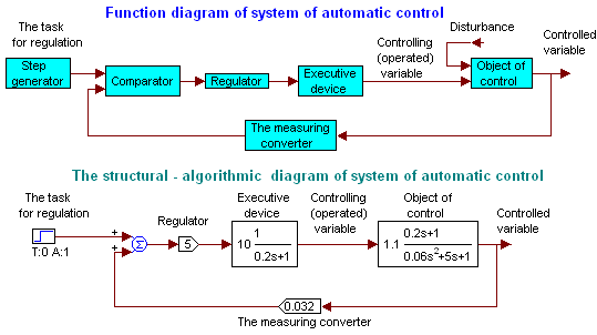
Fig. 1.4. An initial functional diagramme of the ARS (automatic regulatoring system) of a rotational speed of a motor roll of a direct current and its structurally-algorithmic model
Hardware systems and objects consist of units separate, linked and co-operating with each other. And for all system as a whole, and for separate it, properly selected units, it is possible to indicate a place of the application of affecting (of input action) which it is possible to name an entry (input), and a place of their response to an input action named by an output (exit). Both affecting (input action), and response is some physical quantities which are functions of a time.
Models of systems and objects in program VisSim are under construction of separate units - so-called blocks. The unit is virtual analogue of a physical unit of the hardware system. "Virtual" in the given context means imagined (envisioned), physically not existing, implemented program, but from the point of view of the person working with a simulator, the unit is perceived by sight, he is visible on working space VisSim. The term "analogue" guesses, that the unit operates, he submits to the same equations, as a real, modelled (simulated) system component.
Virtual VisSim's units can have or an input on which the output signal of other unit can be given, or an output, which virtual signal can be given on an input of other unit. At last, units can have both an input, and an output simultaneously. Interacting between units is represented by the so-called communication line (wire) a transmitting direction of input actions (signals) from one unit to another.
Interacting between blocks is modelled (simulated) by signals - the functions of a time passed between units on communication line. Signals in model can be measured by means of virtual measuring devices or are observed and investigated by means of the virtual oscilloscope.
Outwardly virtual blocks of VisSim with some extent of conditionality are perceived by the researcher the same as real devices. For example, generators work out signals, Blocks-converters react to input signals in a sense in the same way as actual apparatuses on real input actions, indicating devices display values of signals.
")
Fig. 1.5. (Animation, 25 frames). An exemple of the sequence of operations to removal on working space and an inscription block move of program VisSim 3. Red circles round the cursor conditionally mark out clicks by the left mouse button. For animation activation if the picture does not vary, it is necessary to click by button "Refresh" in a browser top (windows in which you read this text) or it is simple on a picture. For a stopping of some frame that it more in detail to observe, it is necessary to click during the necessary moment by browser button "Stop"
Thus, the principle of construction of model in VisSim consists in removal on working space of models of real units and their connection according to in advance made structurally-algorithmic scheme of a prototype system. Such construction of model from virtual blocks very similar, with known extent of conditionality, on construction of the hardware system from the real blocks (generators, oscilloscopes, and other devices) under production conditions or on a laboratory bench.
VisSim's blocks can be divided into three basic classes and one additional conditionally:
The important builder of model is the connecting line - virtual analogue of physical connection of the units passing affectings from one block to another. Connecting lines in VisSim is unidirectional, pass signals from an output of one block to an input of another. Therefore at model construction it is necessary so to divide the hardware system into function units that the subsequent unit practically did not influence operation of the previous. For example, the output electrical resistance of the previous unit should be much less input resistance of the subsequent unit.
Remarks. Input and output signals can be both single functions of a time, and a gang of such functions. In the latter case the signal is called vectorial, as well as an appropriate input or a block's output.
Generators it is the Blocks having only an output.
Generators work out varying in a time or constant signals.
Exemples of such blocks in VisSim are units:
step (step) ramp (descent, rise(ascent)) sinusoid - sine-wave generator Xmsin (ωt + φ); const - the steady (constant) signal generator, which value does not vary in the course of model work; slider (the sliding contact, a movable indicator)
Fig. 1.6. The important blocks-generators of program VisSim. For a unit location on working space it is necessary to click on Blocks menu, to transfer to point Signal Producer, then to click on a title of the required generator, to translate the cursor in the necessary place of working space and to left mouse button click
Transformers it is the blocks having inputs and outputs.
Blocks-converters are capable to perceive input actions from other blocks, to convert them according to the certain equations or rules and to give a converted signal (the response of the block) on an output.
The major blocks for simulation of linear systems:
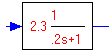 - a transfer function. This block allows to create models both simple, and very complex dinamic units of linear systems and systems as a whole;
Fig. 1.7. The menu for a call of the block a transfer function (transferFunction). The summator and the amplifier are called by selection: Blocks → Arithmetic → summingJunction or gain (amplifier)
The indicators are blocks having only an input
The indicators of the program VisSim are intended for display of signals in the form convenient and habitual for the researcher.
Major indicators are the blocks:
 – plot;
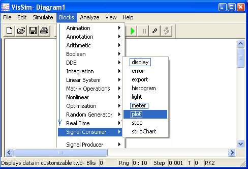
Fig. 1.8. The menu for a call of blocks plot (oscilloscope), display (digital indicator) and meter (analog arrow indicator) - major virtual measuring devices of the program VisSim
As the practice shows, not all students imagine purpose both principles of work and use real, actual oscilloscope. Therefore briefly we shall inform about it.
Oscilloscope is intended for graphic representation during some time interval of dependence of instant size of a researched signal from time.
Fig. 1.9. Exterior of oscilloscope C1-157. Below the cathode ray tube screen input sockets where researched signals move are disposed
Remarks. Now as indicating devices of oscilloscopes screens is liquid-crystal units use.
The oscilloscope basis is a cathode ray tube (CRT). It has the screen on which a beam of the electron gun of a cathode ray tube highlights a small spot. The CRT has the deflecting the beam systems, one of which, is horizontally-rejecting, uniformly displaces a beam, and, therefore, and a spot, on the screen from left to right. Therefore during a time of scan the spot position on the screen on a horizontal axis is proportional to a time. It is a way to present, organise, scan time in space.
On other system of a cathode ray tube deflecting the beam on a vertical, the researched signal varying in a time is given. The cathode ray tube(CRT) deflection yoke is settled so, that beam deflection on a vertical is proportional to an instantaneous value of a researched signal.
Thus, a beam, and, therefore, and a spot on the screen, participate simultaneously in two motions: uniform on level and, according to varying of value of a signal in a time, on a vertical. As a result, on the screen the map of dependence of a signal from a time is gained. Duration of a temporal section during which the signal is watched, is called as a scan time. Oscilloscopes allow to watch periodic signals, the periodic scan which frequency is selected in an integer of times smaller, than frequency of a researched signal in this case uses. At observation of non-cycle signals the beam transverses on the screen from left to right once, and the CRT is selected with the long-lived phosphorescent decay
Fig. 1.10. The oscilloscope deploys dependence of the instantaneous value of a signal on a time on the screen
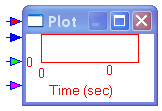
Virtual oscilloscope (plot) of VisSim represents a window similar to the screen of the oscilloscope in which dependence of observable signals on a time (fig. 1.10) is plotted. On an oscilloscope felly conditional maps of inputs to which outputs of other blocks of the diagram for observation of behaviour of their signals depending on a time can be hooked up are located.
The digital indicator ![]() display of VisSim – injects, displays in a digital form value of a signal on an output of that block to which it is connected. This instrument uses for measuring of constants.
display of VisSim – injects, displays in a digital form value of a signal on an output of that block to which it is connected. This instrument uses for measuring of constants.
1.4.4. Inscriptions, remarks, comment, labels
Inscriptions it is blocks without inputs and outputs.
These blocks allow to create on working space of VisSim text fields which help to fathom sense of the diagram and contain informations about the one who when also what diagram has created. The basic unit: label - an inscription.
Model builted in VisSim it is necessary to launch in work, having clicked on the button with green triangle ![]() "Start" (fig. 1.3 and 1.5). As a result of work of model output signals of blocks will start to vary, their values view on the virtual oscilloscope and other indicating devices. The researcher can change parametres of some signals and blocks in the course of model work, other parametres can be changed, having shut down process of work of model. The model operation time can be set before its activation, it is possible and to discontinue work of model at will of the investigator.
"Start" (fig. 1.3 and 1.5). As a result of work of model output signals of blocks will start to vary, their values view on the virtual oscilloscope and other indicating devices. The researcher can change parametres of some signals and blocks in the course of model work, other parametres can be changed, having shut down process of work of model. The model operation time can be set before its activation, it is possible and to discontinue work of model at will of the investigator.
After the model is builted, when on working space the blocks making system are carried out and connected in the necessary order, generators of signals and indicating devices, and also are injected parametres of blocks of model, process of its peration can be launched. For this purpose it is necessary to click on the button with green triangle ![]() "Start" (fig. 1.3 and 1.5).
"Start" (fig. 1.3 and 1.5).
Having gained this command, the program starts to parse how blocks are connected, on the basis of this analysis works out thedifferential-algebraic equations is presenting model and solves them. The gained outcomes as functions of a model time, periodically and very often, are added to values input and output signals of blocks. This ability of the program to execute so difficult, intellectual operations, surprises and admires.
The differential-algebraic equations mathematically present so-called dynamic objects, the objects of very broad class is possessing an inertanceand and number of other properties. And as program VisSim is capable to solve such equations in it it is possible to model (simulate) systems and objects very much a complexity broad band.
The solution of the equations is spent on steps - the small increment of a time is given, are computed, taking into account starting conditions, values of signals on outputs and inputs of all blocks, then the small increment of a time again is given, computations etc. An integration step small value are spent allows the researcher to perceive signals as continuous. Output signals of any block at desire can be watched on the screen of the virtual oscilloscope or to measure the virtual digital indicator. As a result of the solution it is possible to gain dependences of output signals on a time. Thus, work on simulation of systems in program VisSim for the investigator is similar to job on a real bench.
Besides, the program allows to analyze more deeply the gained outcomes and to optimise model. For example VisSim gives a capability of fast graph plottings of frequency characteristics of fragments of model and all system.
Let's illustrate a principle of job of the program Vissim on an example of the simple diagram:
Fig. 1.11. The virtual generator works out a sine-wave signal, the connecting line passes it to an oscilloscope input, the oscilloscope plays back dependence of value of a signal on its input from a time. For example, through 0.25 sec after the simulation beginning (click by button "Start") a generator output signal becomes equal 0.71 arbitrary units, this value А, and is represented by a point in the named instant on the oscilloscope screen
At block removal, i.e. at a location by researcher on working space of the program of the conditional map of the virtual generator, program VisSim makes its description: number, a block position, frequency, amplitude and a starting phase of a sine-wave signal which should work out the generator and puts these data in the special table. Analogous data are recorded at removal on working space of the virtual oscilloscope. At connecning up of an output of the generator to an input of the oscilloscope by means of the connecting line (wire), the program records in description of the diagram generator number from which output there is a signal, both number and an oscilloscope input, on which this signal should act at simulation activation. All data about the diagram find are located in a file of the diagram with .vsm extension, created at diagram saving. For the generator which has been carried out on working space, the program reserves storage location in which will be instants is stored and will vary number, equal to an instantaneous value of an output signal of the generator in this or that. The same mesh forms and for an appropriate input of the virtual oscilloscope.
At activation of simulation program VisSim each clock tick computes a value a generator output signal by formula, displayed on fig. 1.11, corresponding to current value of a time (current clock tick) and puts this value in the storage location retracted for storage of values of an output signal of the generator. During the same clock tick the program determines by means of the connecting line where it is necessary to pass this value and executes transfer. In an observed exemple value is passed from output storage location of the generator in input storage location of the oscilloscope. Further, during the same clock tick of computations, the subprogram of graph plotting of the map of the oscilloscope marks a point on its screen which horizontal co-ordinate is proportional to a time, i.e. to number of current clock tick, and vertical - value of a signal on an oscilloscope input. As a result of repeated multiple execution of these operations at varying of number of clock tick on the oscilloscope screen dependence of an output signal of the generator on a time will be represented (be mapped into).
The basic references

Additional references
5.05.2005 - 22.03.2011
<< Main page. 2. Simulation and simulation programs